Discussion: OCAD12 Issue
in: Orienteering; General
Aug 20, 2019 8:52 PM
#
The last time I tried to process some LiDAR data the program did not properly geo-reference the contour lines to the background maps (vegetation) it generated. In other words the contour lines were on the right side of the screen and the vegetation background map was on the left side of the screen.
Any ideas on what is wrong? I am thinking about trying to re-installing OCAD12.
Any ideas on what is wrong? I am thinking about trying to re-installing OCAD12.
Aug 21, 2019 3:02 AM
#
Am I understanding this correctly that the contour detail and the vegetation detail came from the same LiDAR file at the same time? Yet they popped in to OCAD in separate locations?
Beyond me but for questions such as this OCAD has great customer support.
My go to for checking the accuracy of the geo-referencing of a new map is to go out on the area of the map with a GPS watch, make a track and then see if that track sits correctly on the map in OCAD.
Beyond me but for questions such as this OCAD has great customer support.
My go to for checking the accuracy of the geo-referencing of a new map is to go out on the area of the map with a GPS watch, make a track and then see if that track sits correctly on the map in OCAD.
Aug 21, 2019 7:16 PM
#
Further clarification - is either the vegetation or contours properly georeferenced? It sounds as though you think the vegetation is where it should be and the contours are not but it isn't so absolutely clear I couldn't be inferring more than you intended to imply.
Aug 22, 2019 12:58 PM
#
To tell the truth I do not know which one is correct since I am 550 miles from the site and cannot visit to do a GPS track to check it out. I am just trying to generate a base map at this time.
Aug 22, 2019 3:02 PM
#
Dofishman what have the folks at OCAD said about the issue?
But this may be a naive question. Have you sent the file to anyone else to see what happens?
Naive question #2: have you tried starting over with a new OCAD file just to see if your problem was a one-time glitch?
But this may be a naive question. Have you sent the file to anyone else to see what happens?
Naive question #2: have you tried starting over with a new OCAD file just to see if your problem was a one-time glitch?
Aug 22, 2019 3:02 PM
#
Acme Mapper lets you set a variety of coordinates in "Options", including UTM.
The crosshairs in the middle of the screen is the reference for the coordinate display.
It also has USA Topo maps as a layer option.
I've had glitches (caused by me) where all the objects were selected and an errant click bumped them all to a different location. Typically the rasters are placed by the software and it's much harder to accidently F9 rasters (but it is possible if you're not paying attention).
I've had stuff appear to be "slightly off" but the problem was that it was actually completely ungeoreferenced and it by default loaded in the middle of the screen.
Aug 22, 2019 8:36 PM
#
Dofishman, I'm in the dark here and perhaps others are because we do not know the type of LiDAR file you have and the coordinate system used in the LiDAR.
Could you share?
For instance today I was starting a new map in Florida where some new LiDAR has just been made available on the USGS National Map site.
My standard procedure is to start the map with Open Street Map imported to OCAD and then import the LiDAR. Here we have to be careful that we put in the projection system used for the LiDAR. In the US it could be one of at least three systems UTM (all good there) State Plane (it works well if you can tell OCAD that it is state plane and give it the correct geographic zone) Then there is MTM. I don't know much about it but it is used in Virginia and Quebec.
So I started this map and found that the metadata did not identify the projection system used (a first for me). So first I tried UTM and got a result quite similar to what you experienced. Next I tried State Plane / Florida east and everything went fine.
So could your problem be a misidentified projection system?
Aug 22, 2019 10:11 PM
#
Does OCAD 12 create vegetation from LIDAR data? Or are you talking about Karttapullautin vegetation images?
Aug 23, 2019 12:27 AM
#
OCAD 12 and OCAD 2018/19 basically turn out the same product as KP except with OCAD the contour data is loaded directly into a real map making file where the contour lines can be corrected.
Aug 23, 2019 1:39 PM
#
I emailed the LiDAR data (USGS Lidar Point Cloud MI 16Co-Lapeer 2015 410525 LAS 2018) I down loaded from the National View to OCAD with my issue but I have not received a response.
I have tried to process this data several time and each time I get the same response.
The meta data indicates: Planar Distance Units: Foot.
Coordinates: -83.296, -83.2867, 42.9424, 42.9355
I am using UTM Zone 17.
When processing the data OCAD indicates:
Easting 421000
Northing 539000
When I process Missouri Lidar data I do not have this issue.
Aug 23, 2019 4:21 PM
#
There is a lot of lidar data available that is missing pieces of metadata.
There have been a lot of changes recently when it comes to accuracy and meta data requirements but unfortunately there is quite a bit of data that has some sort of an issue.
There have been a lot of changes recently when it comes to accuracy and meta data requirements but unfortunately there is quite a bit of data that has some sort of an issue.
Aug 23, 2019 6:45 PM
#

it was in feet (xyz), I had to convert it to meter to process it with KP to OOM. I did KP raster vegetation and raw 0.625 m contours and 2.5m contours with auto-interpretation as bezier vectors.
What possibly goes wrong is feet meter thing making xycoordinates go outside coordinates system's bounding box or design plane making it as fallback open them just somewhere visible.
On aerials: link
Aug 23, 2019 6:54 PM
#
The LiDAR in that area is using the State Plane grid coordinate system.
OCAD will handle the conversion to UTM if you tell it that the information is State Plane and identify the correct Michigan zone which is Michigan South..
OCAD will handle the conversion to UTM if you tell it that the information is State Plane and identify the correct Michigan zone which is Michigan South..
Aug 23, 2019 7:01 PM
#
True, those round Easting 421000 Northing 539000 numbers indicate conversion was fine. It's something else then.
Aug 23, 2019 7:44 PM
#
But the northing should be seven-digits for UTM 17 except near the equator. Either David missed a digit or it's a state plate coordinate system.
And again, with the website Acme Mapper with options set to UTM, you can easily see that:
17T 421000 5300000 is about 100km SW of Timmins, Ontario.
And again, with the website Acme Mapper with options set to UTM, you can easily see that:
17T 421000 5300000 is about 100km SW of Timmins, Ontario.
Aug 23, 2019 7:45 PM
#
Also, Jagge, how do you do autointerpretation to Bezier curve vectors? Is this something in OOM?
Aug 23, 2019 11:22 PM
#
The LiDAR in that area is DEFINITELY using the State Plane grid coordinate system.
Aug 24, 2019 8:29 PM
#
Okay, how do I tell OCAD the information is "State Plane"?
When OCAD analyzed the lidar file it gives me
Easting 13420000 and Northing 537500.
When it processes the file it give me background map
Easting 421000 and Northing 539000. I did not miss a digit.
The data is for D bar A scout ranch north of Detroit.
I am going to try to fine a difference for the lidar data
Aug 26, 2019 11:51 AM
#
edwarddes that is nice but how do I reproject the las file? Do I need a special program?
Aug 26, 2019 12:04 PM
#
lastools is a great option to reproject - https://rapidlasso.com/lastools/
Aug 26, 2019 3:51 PM
#
I think you are being led off track by some non-OCAD users.
Using OCAD 12 you are probably using the New Map Wizard and the DEM Import Wizard.Once you open the DEM wizard it will ask you to choose the DEM file and you select your USGS Lidar Point Cloud MI 16Co-Lapeer 2015 410525 LAS 2018
as your Importable File
Right below that it asks you about the coordinate system By default it lists UTM Zone whatever You go to the drop down arrow and it will suggest alternate coordinate systems. You select US State Plane Coordinates System 1983 (ft US) and it will ask you which zone. From the drop down menue you select Michigan South
Also a good idea to check convert height value to meters.
Once you have done that I'm sure you will be away to the races.
Aug 26, 2019 7:28 PM
#
Gord, you were right. Selecting the Michigan South plane and the contour lines come in geo-referenced to the background map. Thank you for the information. Now if I can only get the geotiff USGS maps (NAD 27) to come in referenced to the lidar data. I did a reprojection in QGIS, but it did not seem to work.
I did get a response from OCAD. They said the lidar data was not in UTM 17 format.
I did get a response from OCAD. They said the lidar data was not in UTM 17 format.
Aug 27, 2019 10:59 AM
#
Try this David.
Start the map again using OCAD new map wizard.
It will ask you what type of map then it will ask you where using Open Street Map.
Select the area by narrowing in as close as possible and OCAD 12 will process the OSM data and produce the start of an orienteering map in the symbol set you first selected. Sometimes a few symbols need to be corrected but those are small potatoes. Then go to the DEM Import Wizard and go through the process described above. After some processing time you'll have your O map
By doing that you should not need the USGS map or QGIS
OCAD has given us an automatic transmission where the others are driving stick shifts.
Aug 27, 2019 12:02 PM
#
Hmm, I decided to try the magic in OCAD 12 and it did not work -- after OpenStreetMap dialog, I am getting something about "Cannot read from ....\~A971.osm XML document must have top level element."
Looking at that file, it is empty.
Looking at that file, it is empty.
Aug 27, 2019 4:08 PM
#
igor. That happens to me occasionally. But were you using the New Map Wizard feature?
There may be something in the way the OSM file was created.
Here is a slideshow I created a few years ago to help people make simple O maps from OSM to OOM and to OCAD. Perhaps there will be a clue in there somewhere to help.
There may be something in the way the OSM file was created.
Here is a slideshow I created a few years ago to help people make simple O maps from OSM to OOM and to OCAD. Perhaps there will be a clue in there somewhere to help.
Aug 27, 2019 4:39 PM
#
jima:
I've been getting a similar error message - thought it was something wrong in my system. I've used this (in the New Map Wizard) many times in the past with no issues.
Either something has changed in OSM or OCAD if others are having the problem as well.
Either something has changed in OSM or OCAD if others are having the problem as well.
Aug 27, 2019 6:50 PM
#
Gord, I got the same error message, so I emailed OCAD about this error message. No response yet.
I went to Open Street Map and saved the map of the area of interest. I imported it into a new OCAD map file. When I tried to process (DEM wizard) some lidar data it did not have the correct crt file, so it could not process the data. I also tried to import the OSM file after I processed the lidar data, but that seemed to leave out a lot of the OSM features.
I went to Open Street Map and saved the map of the area of interest. I imported it into a new OCAD map file. When I tried to process (DEM wizard) some lidar data it did not have the correct crt file, so it could not process the data. I also tried to import the OSM file after I processed the lidar data, but that seemed to leave out a lot of the OSM features.
Aug 27, 2019 11:04 PM
#
Here is a slide show that I hope explains the process of getting these LiDAR tiles in to OCAD using the New Map Wizard and DEM Import Wizards available in OCAD 12 and OCAD 2019.
I used this area because I could not find the LiDAR tile referred to above. They are in the same county.
Yes, slides 13 and 14 are left blank. They were intended to show how to use Google Earth and Strava Heat Map in background to add detail to the map but you all know that stuff, right?
I used this area because I could not find the LiDAR tile referred to above. They are in the same county.
Yes, slides 13 and 14 are left blank. They were intended to show how to use Google Earth and Strava Heat Map in background to add detail to the map but you all know that stuff, right?
Aug 28, 2019 12:34 PM
#
The response from OCAD was make sure you have the latest service pack installed or you can save and import the file from OSM. My first attempt to download the latest service pack failed. I will try again later.
Is there an easy way to change symbol sets because OSM brings the map in with a symbol set that is not compatible with the DEM wizard?
Is there an easy way to change symbol sets because OSM brings the map in with a symbol set that is not compatible with the DEM wizard?
Aug 28, 2019 3:42 PM
#
I'm sorry you are not seeing the ease of the method I'm suggesting in the slide show. Is there something I need to clarify?
As to symbol sets I'm not sure you can change the symbol set but you can import additional sets at any time.
As to symbol sets I'm not sure you can change the symbol set but you can import additional sets at any time.
Aug 29, 2019 4:31 PM
#
Gord, after I downloaded the latest service pack I was able to import the data from OSM now I need to get the correct lidar data. At present I have a base map without contour lines.
The lidar data I have did not match the OSM data. I do not know if I have the correct title. I will work on it.
The lidar data I have did not match the OSM data. I do not know if I have the correct title. I will work on it.
Aug 29, 2019 8:33 PM
#
Does anyone know what I am doing wrong? When I import the open street map data it is E 314750-317250 N 4760500-4758000 UTM zone 17. When I process lidar data from Michigan State Plane NAD 83 I get E 13416000-13428750 N 539500-529500.
The two areas are not even close. I am downloading data from the national viewer. The tiles are small so I am using a lot of tiles.
The two areas are not even close. I am downloading data from the national viewer. The tiles are small so I am using a lot of tiles.
Aug 29, 2019 9:10 PM
#
Could you send me the name of the nearest town and a screen shot of the area on open street map? I'll give it a try. gordhun at rogers dot com
As for the state plane data there is one piece of the puzzle you did not mention here but it makes a world of difference: when choosing state plane did you include that the state plane zone is Michigan South?
As for the state plane data there is one piece of the puzzle you did not mention here but it makes a world of difference: when choosing state plane did you include that the state plane zone is Michigan South?
Aug 30, 2019 6:58 PM
#
David---when you download the lidar files, look for the link that says, "Info/Metadata". Right click and open one of them in a new window. Look for a link that ends in "xml". Save that file. I just clicked on the "view" button.
https://www.sciencebase.gov/catalog/item/5acde59ce...
Now search in that file for "proj". You'll find a few "projects", but maybe the third item is, "Latitude of Projection Origin". You can probably search (Ctrl-F) "coord" for coordinates, as well.
Here's part of what that projection section says. I'm adding some bold and underline:
Spatial Reference Information:
Horizontal Coordinate System Definition:
Planar:
Grid Coordinate System:
Grid Coordinate System Name: State Plane Coordinate System 1983
State Plane Coordinate System:
SPCS Zone Identifier: 2113
{this section is the parameters you can use if you can't identify the State Plane number code}
{I use these sometimes to look for the letter designation of the projection in lastools.}
Lambert Conformal Conic:
Standard Parallel: 42.1
Standard Parallel: 43.6666666666667
Longitude of Central Meridian: -84.3666666666666
Latitude of Projection Origin: 41.5
False Easting: 13123359.5800525
False Northing: 0
{Nottice the false easting isn't a round number? That's because the state plane definition is in meters, but they're using it for units in (international) feet. It converts to 4,000,000m.}
Planar Coordinate Information:
Planar Coordinate Encoding Method: coordinate pair
Coordinate Representation:
Abscissa Resolution: 0.000328083989501312
Ordinate Resolution: 0.000328083989501312
Planar Distance Units: Foot
See the two lines above "Foot"? Compare that number to 1/(0.3048). This indicates International Feet and not Survey Feet. 0.3048 is the exact number of meters in a foot assuming 1" = 2.54cm. If that "3.2808..." part is different from 1/(0.3048), it's probably survey feet (where 1" is NOT 2.54cm). And the 3.2808 part will be the same---it will diverge in the later decimal places.
Geodetic Model:
Horizontal Datum Name: GCS NAD 1983 2011
Ellipsoid Name: GRS 1980
Semi-major Axis: 6378137
Denominator of Flattening Ratio: 298.2572221009999052990208776
{end of metadata}
Sometimes 2113 is all you need to know. Look in the las2las readme file for EPSG and SP83 information.
This is a command that hopefully is now in the las2las readme file:
las2las -sp83 help
That lists all of the state planes Martin has already in LASTools. Compare the values of...
Standard Parallel: 42.1
Standard Parallel: 43.6666666666667
Longitude of Central Meridian: -84.3666666666666
Latitude of Projection Origin: 41.5
False Easting: 13123359.5800525
False Northing: 0
...to the lines in that help command that start with "MI". I don't have access to lastools right now. but it might be Michigan South or East or something. Also notice that the list in lastools isn't perfectly alphabetical. It has two or three parts, each separately alphabetical.)
Hopefully you can find that in OCAD to tell OCAD the projection of your files that aren't fitting correctly.
Aug 30, 2019 7:16 PM
#
Aug 30, 2019 7:33 PM
#
Matt, the XML file list state plane coordinate system 1983. It also list plandu . It did not say Michigan south in the meta data.
With Gordon's help I was able to get everything to work. My mistake was not changing the Open Street Map coordinates to state plane. Correct that mistake allowed everything to come in geo-referenced properly.
With Gordon's help I was able to get everything to work. My mistake was not changing the Open Street Map coordinates to state plane. Correct that mistake allowed everything to come in geo-referenced properly.
Aug 31, 2019 3:28 PM
#
David, I don't know why you'd want to change OSM to state plane. You want to import OSM into UTM coordinates in meters (which you have done by your post where you say, "When I import the open street map data it is E 314750-317250 N 4760500-4758000 UTM zone 17."
The problems with using state planes is that they're in feet, and that if you use a GPS set to UTM it's easy to get actual point locations directly from the GPS, while with a state plane that's going to be a huge hassle with a custom UTM setup, if it's even possible.
In LASTools, you can use the letter-based state codes, like OH_S, or epsg codes.
For example, Kentucky is -epsg 3090 or 3091 depending on feet or meters.
I would first try -epsg 2113 in las2las. That should work:
las2las -i input_file.laz -o output_file_UTM.laz -epsg 2113 -feet -elevation_feet -target_utm 16T {I got the T from Acme Mapper.}
But if I want to verify the Michigan South, I do the -help command I posted above. Here are the MI Michigan lines:
MI_N - false east/north: 8e+006/0 [m], origin lat/meridian long: 44.7833/-87, parallel 1st/2nd: 45.4833/47.0833
MI_C - false east/north: 6e+006/0 [m], origin lat/meridian long: 43.3167/-84.3667, parallel 1st/2nd: 44.1833/45.7
MI_S - false east/north: 4e+006/0 [m], origin lat/meridian long: 41.5/-84.3667, parallel 1st/2nd: 42.1/43.6667
You can compare the parameters and see that MI_S is the LASTools code, so that would let you reproject using a command like this:
las2las -i input_file.laz -o output_file_UTM.laz -sp83 MI_S -feet -elevation_feet -target_utm 17T
And I'm sure Gordon will say that OCAD will do this reprojection for you if you can tell it which state plane you are in, and get the feet and surveyfeet correct. But I think he and I would agree that you want your map to use meter coordinates in UTM Zone 17.
Aug 31, 2019 5:48 PM
#
Yes, I agree OCAD will do this reprojection for you if you can tell it which state plane you are in.
David, as I wrote to you earlier it is best to convert the LiDAR tiles to UTM using the OCAD Dem Import Wizard.
David, as I wrote to you earlier it is best to convert the LiDAR tiles to UTM using the OCAD Dem Import Wizard.
Aug 31, 2019 6:20 PM
#
Gordon are you saying when OCAD processes the state plane lidar data it automatically converts it to UTM 17, so GPS data can be imported.
Aug 31, 2019 7:06 PM
#
David, I e-mailed you some slides yesterday.
One of them is a screen shot of the DEM Import Wizard showing you what the screen should look like when importing a State plane file in to a UTM coordinate OCAD.(but only one instead of the dozen or so tiles you need for that camp.)
you tell the program that the DEM files being imported are US State Plane.....Michigan South and the Map is in UTM... Zone 17 north and yes definitely the lidar data is automatically converted to UTM 17 and it works as you can see by the two sample tiles also attached in that e-mail. They are KP -like and contour only tiles of one part of the map you are working on.
The e-mail also explains the process to get there.
Aug 31, 2019 8:49 PM
#
Gordon, OCAD 12 does not convert the map to UTM coordinates. The map DEM wizard says the map is in the state plane coordinate system. This must be a new feature of OCAD 19.
You were also correct that the scale is not correct.
I emailed OCAD to see if they had any suggestions.
You were also correct that the scale is not correct.
I emailed OCAD to see if they had any suggestions.
Aug 31, 2019 10:52 PM
#
Dofishman: OCAD 12 allows all kinds of coordinate system transformations, including during the DEM import process. See the ‘Coordinate System’ section here:
https://ocad.com/wiki/ocad12/en/index.php?title=DE...
If your map isn’t in UTM because of a previous import without transformation, you can go to Map > Transform > Change Coordinate System, and transform it, too.
https://ocad.com/wiki/ocad12/en/index.php?title=Ma...
https://ocad.com/wiki/ocad12/en/index.php?title=DE...
If your map isn’t in UTM because of a previous import without transformation, you can go to Map > Transform > Change Coordinate System, and transform it, too.
https://ocad.com/wiki/ocad12/en/index.php?title=Ma...
Aug 31, 2019 11:52 PM
#
dofishman did you ever try following these steps? The conversion happens so seamlessly the OCAD mappers - you and I - don't even see it happening. It's the mappers of other programs that have to jump through those hoops Cedar creek describes.
With a large map (12+ LiDAR tiles) such as yours there are a couple of other things to note. It helps to have a computer with a lot of processing capability and you should be using he OCAD 64 bit version. Even with that you will need patience while the computer does its work and when the screen tells you OCAD is not responding hang in there. It is likely to still be working behind the scenes.
With a large map (12+ LiDAR tiles) such as yours there are a couple of other things to note. It helps to have a computer with a lot of processing capability and you should be using he OCAD 64 bit version. Even with that you will need patience while the computer does its work and when the screen tells you OCAD is not responding hang in there. It is likely to still be working behind the scenes.
Sep 1, 2019 12:26 PM
#
Hughmac thanks for the information. Using the transform function I was able to transform the map to a UTM coordinate system. Unfortunately it did not transform the background maps.
Sep 1, 2019 4:09 PM
#
What kind of background maps are these? Where are they from? Maybe remove and re-Open these background map files, experimenting with New Offset vs Existing Offset and Angle?
Sep 1, 2019 8:14 PM
#
David, If the background maps are from the previous run in the wrong coordinate system, you can try to figure out how to assign the state plane CRS to those old background maps, or you can just recreated them in OCAD with the UTM coordinate system.
Sep 2, 2019 8:44 PM
#
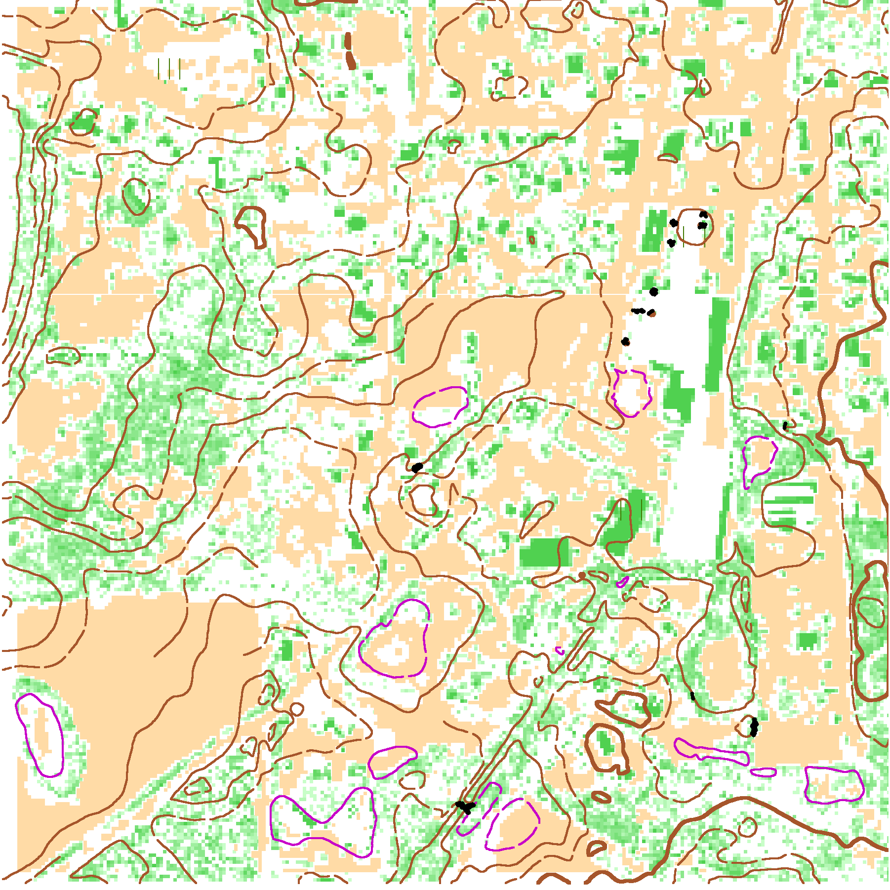
With the help of gordhun. hughmac, cedarcreek and OCAD I figured out all the mistakes I was making. In reality generating a base map in OCAD is pretty simple. All it takes is five basic steps.
1. Download Lidar Data
2. Determine Lidar Data Coordinate System and Units
3. Open OCAD New Map Wizard and Import Open Street Map Data
4. Use DEM Wizard to Process Lidar Data
5. Export Partial Map of Desired Area
The key is using the proper coordinate system. The background maps came in correctly and I was able to load in an aerial image too.
This discussion thread is closed.